
Goal this week is to redraw the echo hello-world board and adding at least an LED and a push button to it
During my prefab academy I used kokopelli for PCB design. Now I trying EAGLE for redraw the echo hello world board (shown in below)
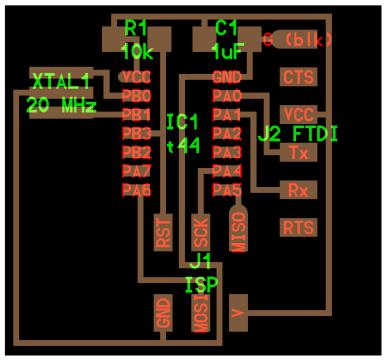
and adding atleast a LED and a push button.
After install Eagle i go through some online Eagle tutorials .
In this tutorial on CadSoft Eagle, I got how to program up and running, how to navigate the interface, how to design your first schematic, and how to use DesignConnect to build a Bill-of-Materials
For re-draw the schematic diagram of echo hello world board, i use fab library for add components to schematic of echo hello world board. After downloading fab library place it into the " lbr " folder of Eagle software
I use LED series resistance calculator (LED CENTER), this is good for when you have an LED and need to know "what resistor should you use with your LED?" This calculator determines that for you.

Diode forward current (mA) get from led data-sheet . - The value was 470 ohm then I use 499 ohm resistors.
Components used in redesigned echo hello world board are
Design the PCB
Then I start to draw the schematic of the board , there are the steps to do it:
1.- First i install Eagle.
2.- Download FabLab library (library of components) and place it into the lbr folder in your Eagle installation
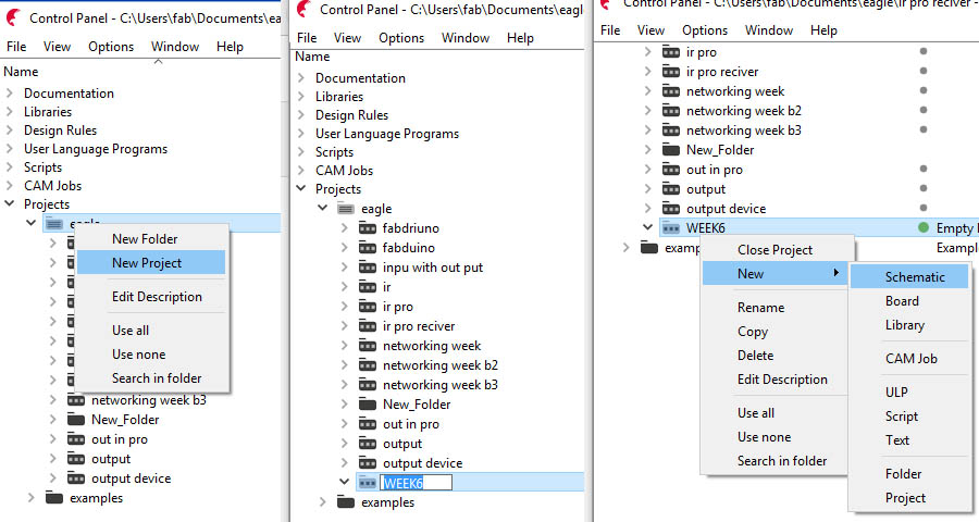
3.- Open Eagle, create New Project and add new Schematic File
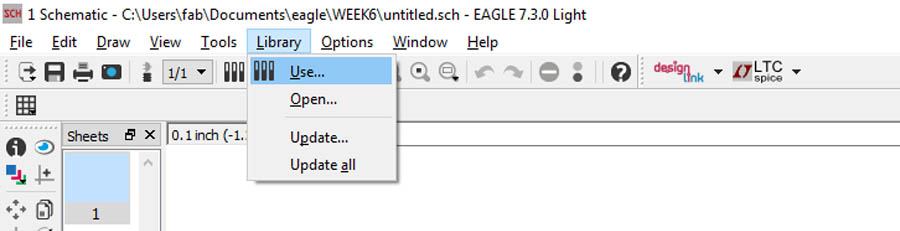
4 .Switch to Eagle and click the menu item for "Library > Use", and select fab.lbr and click open, to use FabLab Library in your projec
5 .Browse and add all electronic componets for PCB.
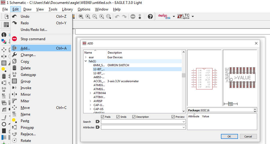
First i added all the components in echo hello world boar , and add extra two LED and a switch .Then I start to Wire the components of board and.
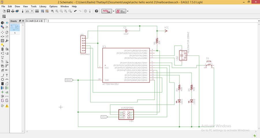
Download schematic file ( .sch )
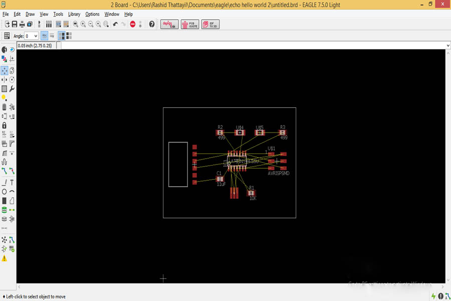
After completing schematic, then switch to board (option for arrange the components on the board )
Then I arrange the components as I need to be in the PCB
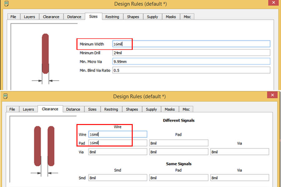
6 .Before Routing the Board set minimum width and clearance of wire, pads and via (i am not using via on this board ) , for this
" Edit > design rules "
I am using 1/64 inch bit for mill the traces (1/64 inch = 15.625 mill) . So i set Trace width and clearance as 16 mill ( default 8 mill) for avoiding missing of traces and pads
In manually Routing the Board, arranging each of those wires into the bottom or top copper traces (for double-side PCB use both bottom and top copper traces). At the same time, you also have to make sure not to overlap two different signals (or wires ).

In Autoroute all the above arrangements check automatically by the software During Auto routing the Board. After arranging all components, Autoroute it.several times I arrange positions of components for getting perfect position of components without jumpers in board
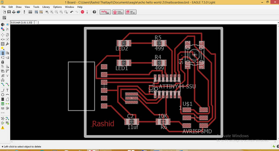
Download boad file ( .brd )
Then Export the layout for mill and cut, as a monochrome png at 500 dpi. Here is the output:
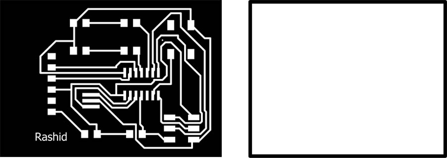
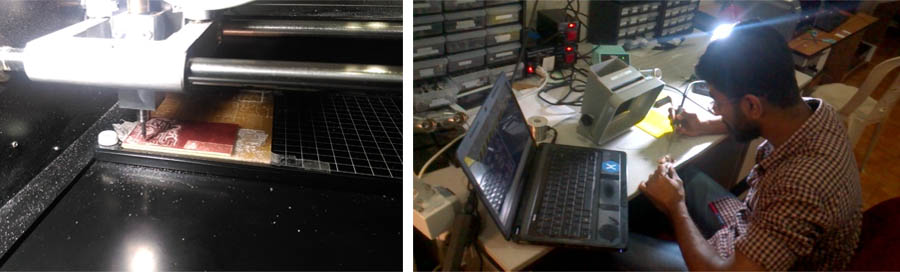
Check all the traces are correct then milled the PCB .Last step was stuff the board.
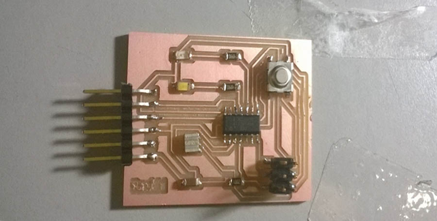
Here is the completed board
Download mill file ( .png )
Download cut file ( .png )
all files (.zip)
I use Proteus to simulate the PCB . Proteus also can use for design schismatic and board . Fist I start to create an schematic circuit of my above designed board in Proteus for this Open Proteus and create New Project.
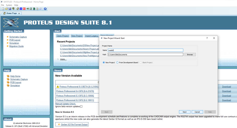
After selecting the path to save project saves click on Next.
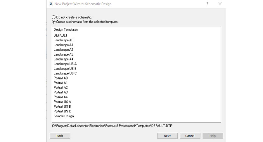
Then Create an empty schematic file . For this select " DEFAULT " design template then click Next.
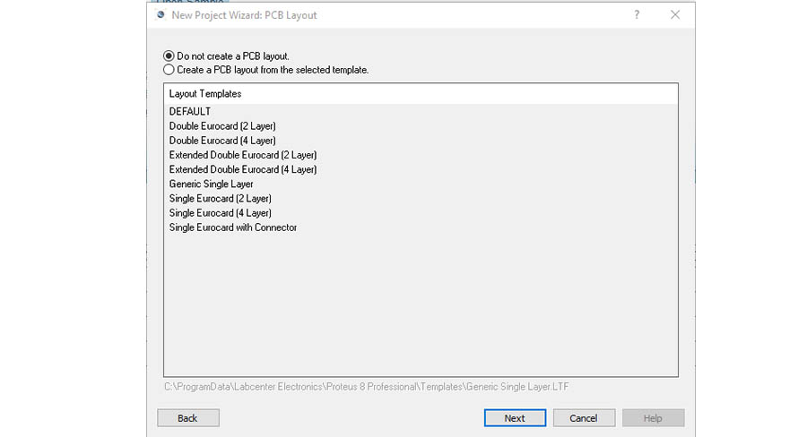
I already designed PCB in eagle software so In this time not need to create a PCB layout because I only need to simulate above designed PCB . So I select " DO not create PCB layout "" and then Push on Next.
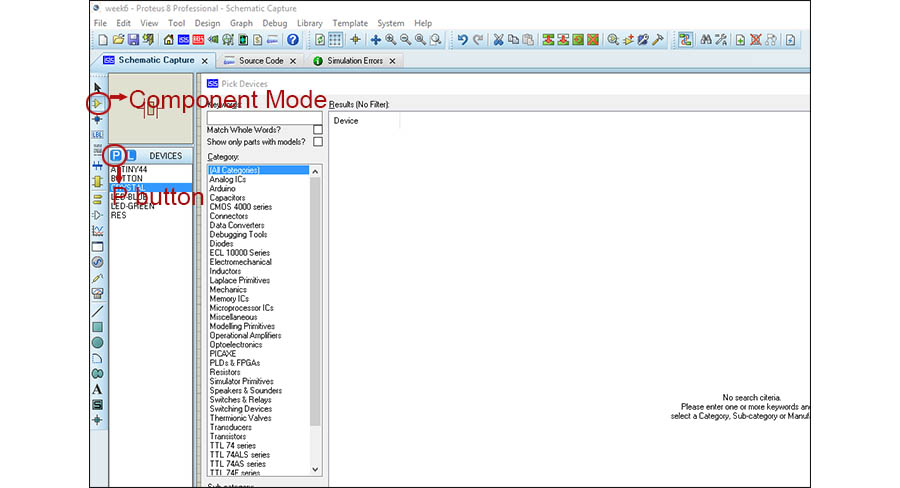
Don't create firmware Project, click Next and Finish. Now I need open components for my schismatic . For open components library click on Component Mode button and then click P button . Now open components library from this Search and add the electronic components.
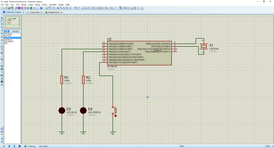
After adding all component make a proper Place and wire the components
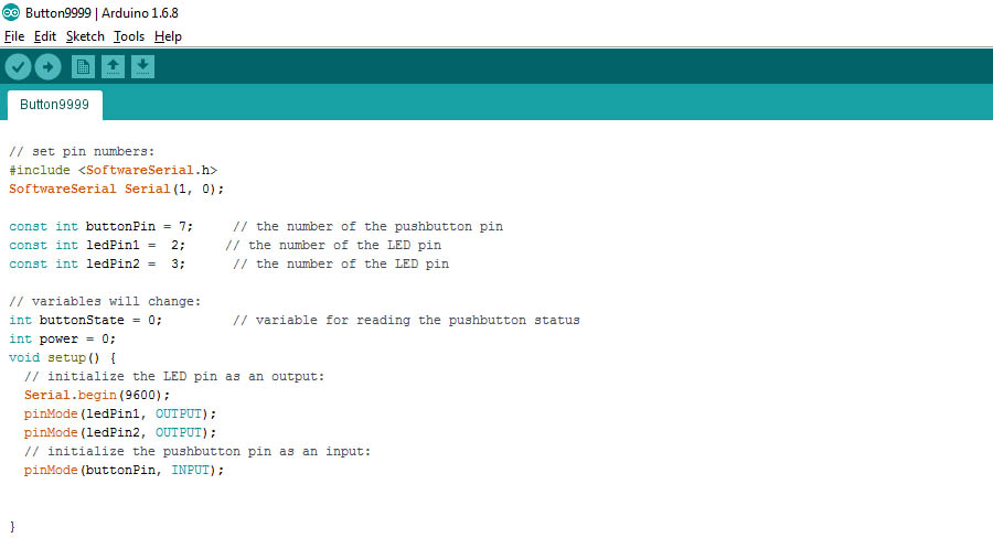
For simulating this circuit need burn a program into microcontroller used in this circuit. Here I am using Attiny 44 as a microcontroller. Then I start to write a simple program in Arduino IDE
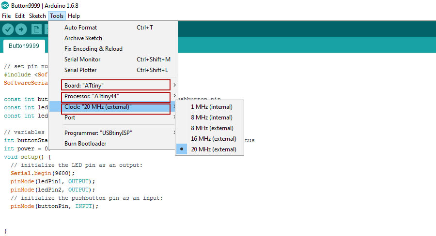
Secondly, I want to configure my board then I select tools, in her, I want to program the Attiny board for that select Board:"Attiny".Then I choose processor:"ATtiny44" and
select clock:"20 MHZ(external)"
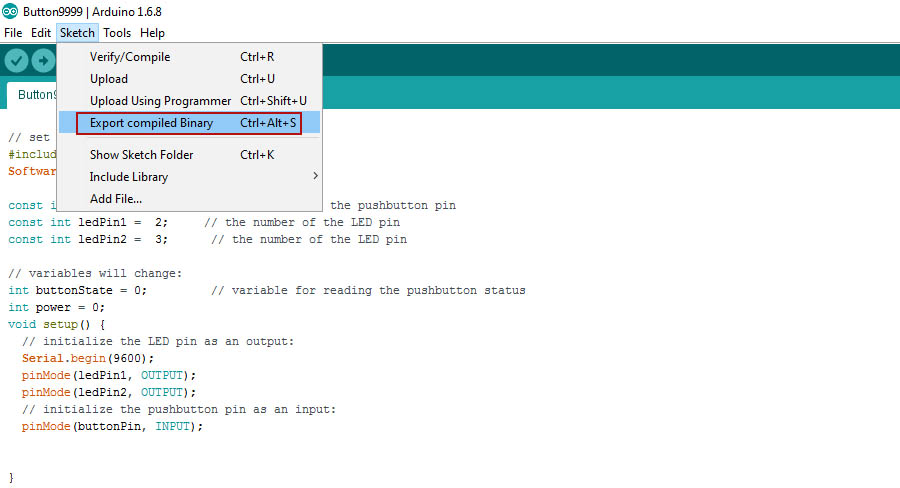
Then go to Sketch and select Export Compiled Binary to generate HEX file.
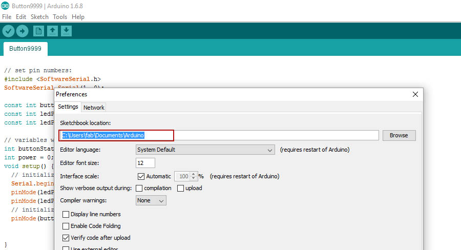
generated HEX file was saved on the location show below
Simulate :
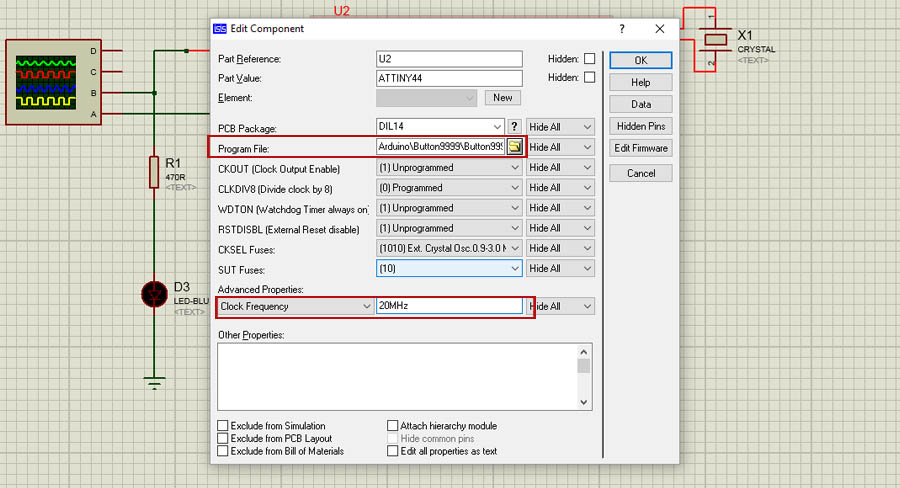
Now, is time to upload the HEX file in schematic circuit:
1.- Double click on ATtiny44 and push on folder button to browse HEX file.
2.- On Clock Frequency set 20MHz.
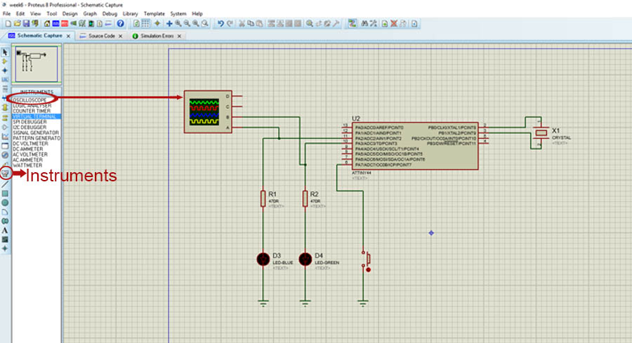
Add some Virtual Instruments:
1.- Push on Instruments button.
2.- Add Oscilloscope to monitore the PWM output.
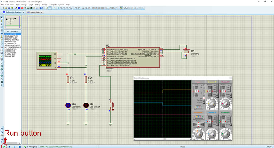
Finally push on Run button
Download Proteus File)